
Home > Movie gallery
On this webpage, you can view and download a collection of movies about our current research. More pictures and photographs can be found in our slideshow.
All movies have been saved in the animated .gif format, because of compatibility reasons. High resolution movies are available upon request.
| [1] |
|
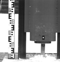
Axial crushing of pultruded circular composite tube under drop weight impact [2.4 MB] This movie shows the axial impact and consequently crushing of a pultruded composite tube with circular cross-section. A steel mass of 80 kg is falling from 5 metres, with the small composite tube attached to its bottom. As you can see, the mass is decelerated in a very smooth way and there is almost no rebounce, which means that almost all energy has been absorbed by the crushing of the composite tube. |
| [2] |
|
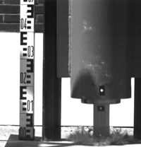
Axial crushing of pultruded square composite tube under drop weight impact [2.6 MB] This movie shows the axial impact and consequently crushing of a pultruded composite tube with square cross-section. A steel mass of 80 kg is now falling from 8 metres, with the small composite tube attached to its bottom. As you can see, the mass is again decelerated in a very smooth way and there is almost no rebounce, which means that almost all energy has been absorbed by the crushing of the composite tube. |
| [3] |
|
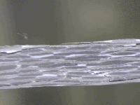
Visualization of fatigue damage in carbon thermoplastic composite with online video microscopy [5.8 MB] A five-harness satin weave carbon/PPS thermoplastic composite is tested in tension-tension fatigue. A microscope, mounted close to the specimen, records a video of the polished edge during fatigue loading. |
| [4] |
|
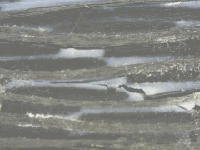
Visualization of fatigue damage in carbon thermoplastic composite with online video microscopy (larger magnification) [8.2 MB] |
| [5] |
|
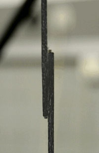
Single lap shear fatigue testing of a fusion bonded joint in a carbon/PPS thermoplastic composite [2.4 MB] Two laminates of a 5-harness satin weave carbon/PPS laminate have been fusion bonded through infrared welding. Extra PPS sheets have been added in the fusion bond. This video shows the tension-tension fatigue testing of the single lap shear joint. |
| [6] |

|
First eigenmode of a 49 metre composite wind turbine blade [0.2 MB] Meshing tools have been developed for quasi-automated meshing of large wind turbine blades. The ply stacking sequence is built up from the mould side and the location of ply drop-off's, sandwich sections (with balsa wood or PVC foam), shear webs and main girders is automatically generated. The adhesive joints for the shear webs and at the leading and trailing edge are modelled explicitly with solid elements, representing the correct thickness of the adhesive bond along the blade length. The movie shows the first eigenmode of a 49 metre wind turbine blade, made from glass fibre/epoxy composite. |
| [7] |

|
Second eigenmode of a 49 metre composite wind turbine blade [0.4 MB] |
| [8] |

|
First torsional eigenmode of a 49 metre composite wind turbine blade [0.4 MB] |
| [9] |
|
Simulation of the Mode I fracture toughness test of a two-component epoxy adhesive [0.3 MB] This movie shows the progressive failure of a two-component epoxy adhesive when tested in Mode I. Cohesive elements are used to model the cohesive failure in the adhesive bond. |
| [10] |
|
Simulation of the Mode I Double Cantilever Beam (DCB) test of a composite laminate [1.4 MB] A Double Cantilever Beam (DCB) test is a standard test to measure the mode I fracture toughness of a composite laminate. A pre-crack is realized by inserting a Teflon film at the midplane of the laminate. This movie shows a simulation with cohesive elements, representing the progressive delamination in the DCB test specimen. |
| [11] |
|
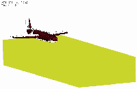
Full-scale SPH simulation of ditching of a Airbus A319 aircraft on water [1.9 MB] After the emergency landing of an aircraft on the Hudson river, a renewed interest is seen for simulation of ditching of aircrafts on water. This movie shows a full-scale simulation of ditching of a Airbus A319 aircraft on water. The Smoothed Particle Hydrodynamics (SPH) method is used to represent the water. The aircraft model is a deformable shell model. The wing span of the aircraft is 34 m, and the length of the aircraft is also about 34 m. The SPH grid counts nearly 2 Million elements, with each particle weighing about 8 kg. The particles are still too large to accurately simulate the water splash, but the calculation time for an ever finer grid is excessively large. |
| [12] |
|
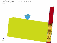
Full-scale SPH simulation of the wave motion of a floating LIDAR mounted on a 50 tonnes buoy [2.7 MB] LIDAR stands for Light Detection And Ranging. The laser points vertical to the sky and measures the wind velocity profile in function of the height above sea level. This wind velocity profile is important information for off-shore wind turbines, because given the very large rotor diameters, the wind speed can vary considerably from the lowest to the highest point of the rotor diameter. This movie shows the simulation of the stability of the 50 tonnes buoy that carries the LIDAR. The more stable the buoy is, the less stabilizing must be done for the LIDAR itself. The Smoothed Particle Hydrodynamics (SPH) method is used to represent the water, and a paddle is used to generate the waves. |
| [13] |
|
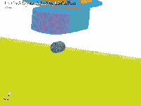
Detailed view of the full-scale SPH simulation of the wave motion of a floating LIDAR mounted on a 50 tonnes buoy [13.4 MB] |
| [14] |
|
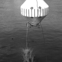
Bottom slamming test on filament wound composite buoy [4.6 MB] A filament wound composite buoy (diameter and height about 1.8 metres) is dropped onto a calm water surface to simulate bottom slamming. Slamming is the technical term for wave impacts with a short duration and high peak pressures on a floating/sailing structure. The buoy was instrumented with pressure sensors, accelerometers and strain gauges. These tests were done in the framework of the European FP6 project SEEWEC. |
| [15] |
|
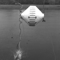
Lateral slamming of filament wound composite buoy [4.4 MB] Another filament wound composite buoy (same dimensions) was dropped onto the water surface. This configuration simulated lateral slamming (or breaking wave slamming). For this geometry, lateral slamming is far more severe than bottom slamming. In these tests, the effect of the deformability of the structure on the peak pressures was also assessed. |
| [16] |
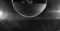
|
High speed recording of vertical water entry of a quasi-rigid cylinder [3.4 MB] A quasi-rigid cylinder is dropped from a certain height and accelerated towards a calm water surface. A high-speed camera is positioned outside the water tank and records the vertical water entry of the cylinder. The cylinder is instrumented with local pressure sensors and strain gauges, and the dynamic impact force is measured and synchronized with the high speed images. |
| [17] |
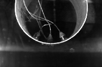
|
High speed recording of vertical water entry of a deformable cylinder [4.2 MB] A deformable cylinder is dropped from a certain height and accelerated towards a calm water surface. A high-speed camera is positioned outside the water tank and records the vertical water entry of the cylinder. The cylinder is instrumented with local pressure sensors and strain gauges, and the dynamic impact force is measured and synchronized with the high speed images. This research focuses on the comparison of the slamming pressures and forces for quasi-rigid and deformable objects. |
| [18] |
|
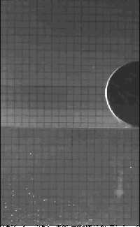
High speed recording of the vertical water entry of a quasi-rigid cylinder [2.1 MB] This movie shows the vertical water entry of a quasi-rigid cylinder, that is falling between two closely spaced glass walls. As such, the measurement can be compared with a 2D simulation. |
| [19] |
|
Corresponding ALE simulation of the vertical water entry of a quasi-rigid cylinder [0.5 MB] This movie shows the corresponding 2D simulation of the vertical water entry of a quasi-rigid cylinder. The Arbitrary Lagrangian-Eulerian (ALE) method has been used to simulate the impact. Benchmark simulations have been done with Smoothed Particle Hydrodynamics (SPH) and Computational Fluid Dynamics (CFD), comparing pressures, forces and water profiles. |
| [20] |

|
Three-dimensional numerical simulation of dam breaking with Smoothed Particle Hydrodynamics (SPH) [1.7 MB] The dam break model is a well-known benchmark for simulation of violent flows. It is based on an experiment from Marin in the Netherlands, where a volume of water (initially in rest) is suddenly released. It flows towards a rigid object, instrumented with pressure sensors. The water height is measured over time at different locations. This movie shows the numerical simulation of the dam break model with Smoothed Particle Hydrodynamics (SPH). |
| [21] |
|
Three-dimensional numerical simulation of dam breaking with Smoothed Particle Hydrodynamics (SPH) (side view) [1.2 MB] The dam break model is a well-known benchmark for simulation of violent flows. It is based on an experiment from Marin in the Netherlands, where a volume of water (initially in rest) is suddenly released. It flows towards a rigid object, instrumented with pressure sensors. The water height is measured over time at different locations. This movie shows the numerical simulation of the dam break model with Smoothed Particle Hydrodynamics (SPH). |
| [22] |

|
Wave runup against a vertical cylinder in the wave flume in Hannover [1.9 MB] High speed recording of a wave runup against a vertical cylinder in the wave flume in Hannover, the biggest wave flume in Europe. This scale model was built to study the wave runup against the tower of offshore wind turbines. |
| [23] |
|
Simulation of the motion of a wave energy converter in a regular sea state (pencil shape) [0.5 MB] |
| [24] |
|
Simulation of the motion of a wave energy converter in a regular sea state (rectangular shape) [0.4 MB] This movie shows a simple example of a coupling code that has been developed to simulate and optimize the power extraction of wave energy converters. The Smoothed Particle Hydrodynamics (SPH) method is used to generate the waves. The wave energy converter is represented by a rigid or deformable body that is floating in the water. The anchoring to the seabed can be taken into account as well. The energy extraction devices inside the wave energy converter are modelled with multi-body dynamics software. The kinematics of generators, gear boxes, dampers, bearings, etc. can be modelled. The coupling code updates the position of the buoy in every time step, depending on the wave motion and the power extraction. |
| [25] |
|
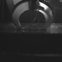
High-speed recording of slamming of hollow filament wound cylinder [3.0 MB] A hollow filament wound cylinder is slammed onto the water surface in a laboratory set-up. The cylinder was made very deformable on purpose, and the measured peak pressures and strains were compared with those in a quasi-rigid cylinder, this again to assess the effect of the deformability of the structure on the peak pressures. |
| [26] |
|
FEM simulation of slamming of hollow filament wound cylinder (structural analysis) [0.3 MB] Fully coupled simulations of the slamming experiment of the hollow filament wound cylinder have been done with the commercial CFD code Fluent and structural code ABAQUS. The coupled simulations take care of the fluid-structure interaction and the effect of the deforming structure on the peak pressures in the water and vicev versa. This movie shows the deformation of the structural part in ABAQUS. The Tsai-Wu measure (a failure index for composite materials) is shown. |
| [27] |
|
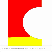
FEM simulation of slamming of hollow filament wound cylinder (CFD analysis) [0.1 MB] This movie shows the same fully coupled simulation of the slamming experiment of the hollow filament wound cylinder, but this time the result in the CFD code Fluent. The red area is air, and the yellow area is water. The water jet that is formed at the bottom of the cylinder, can be clearly seen. |
| [28] |
|
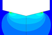
Peak pressures in slamming of rigid cone on the water [0.2 MB] This CFD simulation in Fluent shows the distribution of the peak pressures when a rigid cone is slamming onto the water surface. The peak pressures are clearly very localized and travel very fast along the contact surface. |
| [29] |
|
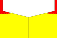
Water uprise in slamming of rigid cone on the water [0.1 MB] For the same CFD simulation, the water uprise is shown along the rigid cone. The red area is representing air, the yellow air the water. A volume-of-fluid (VOF) technique was used to reconstruct the water surface. |
| [30] |
|
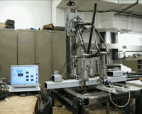
Fatigue test of a composite racing bicycle frame according to the European testing standard EN 14781 [6.3 MB] Every new design of a racing bicycle for professional cycling has to pass the fatigue test prescribed by the EN 14781 standard. The pedalling action is |
| [31] |

|
Kinematic simulation of the dynamic response of a composite racing bicycle to road accelerations [0.4 MB] |
| [32] |
|
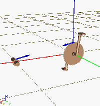
Kinematic simulation of bicycle chain pedalling [0.6 MB] |
| [33] |

|
Precessing motion of a vertical axis wind turbine with small mass imbalance of the blades under wind gust loading [0.2 MB] |
| [34] |
|
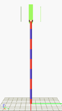
Kinematic simulation of the first eigenmode of a vertical axis wind turbine with multibody dynamics [0.3 MB] |
| [35] |
|
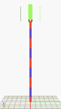
Kinematic simulation of the second eigenmode of a vertical axis wind turbine with multibody dynamics [0.3 MB] |
| [36] |
|
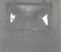
Bird strike test on an aluminium plate [1.7 MB] |
| [37] |
|
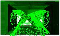
Corresponding simulation of the bird strike experiment on an aluminium plate [5.8 MB] |
| [38] |
|
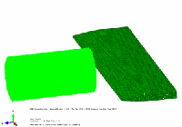
SPH simulation of a gelatin bird splitter test [0.9 MB] |
| [39] |

|
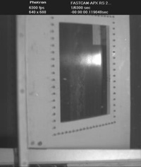
Bird strike test on riveted aluminium plate [2.6 MB] This movie shows the effect of the impact of a bird on a riveted aluminium plate. The high-speed camera is mounted on the roof of the impact chamber. Basically, you are looking in top view on the experiment. The bird is coming from the left, and you see the top edge of the clamping frame. Behind that clamping frame, a mirror is mounted under 45 degrees, and in the camera view, you see the back side of the aluminium plate through the mirror. In the mirror view, you clearly see the rivets and the grid applied to the aluminium plate. |
| [40] |
|
Bird strike test on riveted carbon thermoplastic composite plate [2.3 MB] The same test with the same camera position is repeated for a riveted composite plate. The behaviour is much more elastic, with large deflections and vibrations, but quasi-zero permanent out-of-plane deformation of the plate. |
| [41] |

|
Projection moire measurements of bird strike test on composite plate [0.8 MB] In this movie, the camera is positioned to view the back side of the impacted plate. The bird is coming from behind. Moire grating lines are projected onto the back side of the composite plate. During the bird strike impact, the deflection of the grating lines gives information about the instantaneous out-of-plane displacements. In this case, a higher impact speed was used and the bird is penetrating the plate. This movie clearly shows that if the speed is high enough, the plate is already penetrated by the bird before the boundaries of the plate "feel" the impact. |
| [42] |

|
Projection moire measurements of bird strike test on composite plate (optimized
contrast and brightness) [1.2 MB] The recording conditions for such a projection moire set-up are very stringent. The frame rate of the high-speed camera is about 12 000 frames per second, and the diaphragm should be closed as much as possible to have a large depth of focus. Therefore, the captured light on the CCD of the high speed camera is very small and the original movie is very dark. This movie has been processed and contrast and brightness have been adjusted to generate a more clear view. |
| [43] |
|
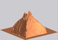
Processed projection moire results of bird strike test on composite plate [0.2 MB] After applying Windowed Fourier Transform, the projection moire images can be converted to out-of-plane displacements. This movie shows the 3D plot of the instantaneous out-of-plane displacements during the bird strike impact of a composite plate. The phase unwrapping is very difficult in this case, due to the large number of discontinuities in the phase field. |
| [44] |
|
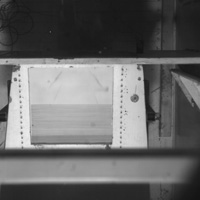
Bird strike test on aluminium plate with geometric moire [2.4 MB] In this movie, the camera set-up is very similar. You are looking again in top view on the experiment. The bird is coming from the top of the image, and you see the top edge of the clamping frame. Behind that clamping frame, a mirror is mounted under 45 degrees, and in the camera view, you see the back side of the aluminium plate through the mirror. In the mirror view, you clearly see the rivets and the moire lines applied to the aluminium plate. In this experiment, geometric moire is applied, because the grating lines are not projected, but drawn on the back side of the plate. |
| [45] |
|
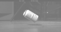
High speed image recording of a drop test on a fluid filled beverage can [2.0 MB] |
| [46] |
|
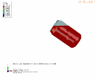
Simulation of a drop test on a fluid filled beverage can (side view) [0.4 MB] |
| [47] |

|
Simulation of a drop test on a fluid filled beverage can (bottom view) [1.3 MB] |
| [48] |
|
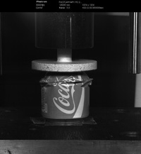
Axial crushing of an empty metal beverage can without entrapped air under drop weight impact (drop height 0.5 m) [1.1 MB] In this movie, a cola can is crushed in a lab-scale drop weight set-up. Again, this demonstration case was mainly used to calibrate the set-up and extend the measurement facilities. This drop weight set-up is equipped with a dynamic force sensor, accelerometer, inductive displacement sensor, strain gauges and high speed camera, and all signals are sampled on the same time basis. That means that instantaneous force, deceleration, position, strain and global deformation can be captured all at the same time. |
| [49] |
|
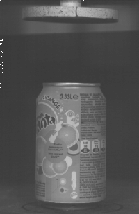
Axial crushing of an empty metal beverage can without entrapped air under drop weight impact (drop height 1.25 m)[4.3 MB] |
| [50] |
|
Simulation of the axial impact test on an empty metal beverage can without entrapped air (drop height 1.25 m) [0.5 MB] |
| [51] |
|
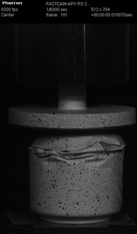
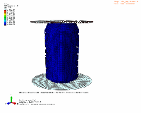
Axial crushing of an empty metal beverage can with entrapped air under drop weight impact (drop height 1.25 m) [0.8 MB] In this movie, the cola can and impactor on top have been sprayed with a speckle pattern to apply Digital Image Correlation (DIC). This procedure has been developed, amongst other reasons, to verify the derived speed and dynamic contact force, calculated from the DIC measurements, with the readings from the force sensor and inductive displacement sensor. The measurements appear to match perfectly. |
| [52] |
|
Simulation of the axial impact test on an empty metal beverage can with entrapped air (drop height 1.25 m) [1.4 MB] |
| [53] |
|
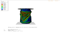
FEM simulation of axial crushing of metal can under blast loading [0.6 MB] This movie shows a finite element simulation of a blast loading on a metal can. The commercial finite element code ABAQUS/Explicit was used here. This experiment is only a demonstration case for the blast loading on composite tubes. The detonation of the blast charge is not simulated here, but the experimentally measured pressure profile on the top plate is imposed as a boundary condition in the simulation. The maximum deformation length and deformation pattern match very well with the experiments. |
| [54] |
|
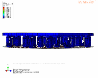
Large-scale blast test on an array of empty metal beverage cans [4.3 MB] |
| [55] |
|
Simulation of a large-scale blast test on an array of empty metal beverage cans [0.1 MB] |
| [56] |
|
Large-scale blast test on an array of pultruded composite tubes [4.6 MB] |
| [57] |

|
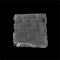
Micro-tomography of three stacked 5-harness satin weave carbon fabric composites (lateral cross-cut) [1.2 MB] This movie shows a lateral cross-cut of three laminates (taped together) of a 5-harness satin weave composite, measured with micro-tomography. |
| [58] |
|
Micro-tomography of three stacked 5-harness satin weave carbon fabric composites (top-bottom cross-cut)[1.6 MB] This movie shows a top-bottom cross-cut of the same three laminates (taped together) of a 5-harness satin weave composite, measured with micro-tomography. |
| [59] |
|
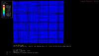
Longitudinal strain eps_xx in a stack of 4 unit cells of a 5-harness carbon satin weave textile composite [0.9 MB] This movie shows a top view of a stack of 4 unit cells of a 5-harness carbon satin weave composite, loaded in uniaxial tension. The strain eps_xx in the loading direction is shown on the free top surface. The local strain variations inside the unit cell can be clearly seen. |
| [60] |
|
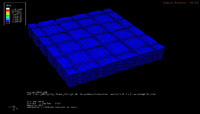
Transverse damage in a stack of 4 unit cells of a 5-harness carbon satin weave textile composite [1.0 MB] This movie shows a 3D view of the same stack of 4 unit cells of a 5-harness carbon satin weave composite, loaded in uniaxial tension. This time, the directional damage is taken into account. As expected from the local strain variations, the damage initates first in the transverse yarns. |
| [61] |
|
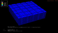
Transverse damage in a stack of 8 unit cells of a 5-harness carbon satin weave textile composite [1.2 MB] This movie shows a 3D view of a stack of 8 unit cells of a 5-harness carbon satin weave composite, loaded in uniaxial tension. Again the directional damage is shown. Different stacks were studied to assess the effect of perodic boundary conditions, symmetry conditions and free surface effects. |
| [62] |
|
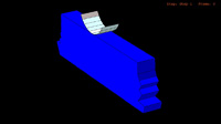
Frictional contact between rigid pin and composite plate (top-bottom cross-cut)[0.4 MB] Finite element simulation of the sliding contact of a rigid pin on a composite plate. In many cases, the through-the-thickness stiffness of a composite bearing is quite low and the contact stress distribution cannot be modelled anymore by Hertzian contact formulas. |
| [63] |
|
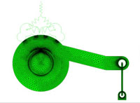
Simulation of large-scale test set-up for friction and wear testing of radial composite bearings in dry sliding contact [0.4 MB] |
| [64] |
|
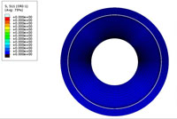
Evolution of the radial stress distribution in the contact zone of a radial composite bearing and a metal shaft under wearing conditions[0.75 MB] |
| [65] |
|
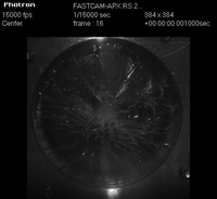
Impact of hemispheric steel impactor on circular glass plate [1.1 MB] In this movie, the same lab-scale drop weight set-up is used to impact glass plates with and without security film. Through a mirror in the base support of the drop weight set-up, you look to the back side of the glass plate. In the first frames of the movie, you can see through the glass plate the circular indentor of the impactor coming from behind. You cannot really see the cracks in the glass propagating with small increments, because the travelling speed of the cracks is so large, that you need a very high frame rate (around 100 000 fps), but then the resolution is very limited and you do not have a field view of what is happening. |
| [66] |
|
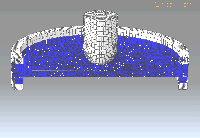
Simulation of the brittle failure of monolithic float glass under lateral impact [4.9 MB] |
| [67] |

|
Simulation of the post-failure response of laminated glass under impact with a rubber indentor [2.1 MB] |
| [68] |
|
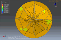
Bottom view of the simulation of the post-failure response of laminated glass under impact with a rubber indentor [1.8 MB] |
| [69] |
|
Projection moire measurement of impact of foam impactor on circular
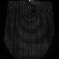
glass plate with safety film applied [1.8 MB] This movie shows a recording of the impact of glass plate retrofitted with security film, by a steel impactor. The glass plate has a much larger diameter now, and you can only see a sector of the circular plate, from the edge of the circular support till a little bit beyond the centre of the plate. Again, projection moire is used to measure the instantaneous out-of-plane displacements. |
| [70] |
|
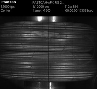
Pendulum impact of inflated tyre on large glass panel with safety film applied
(EN12600 standard for human impact) [3.6 MB] In this movie, the impact of a large glass pane (2 m x 1 m) with security film is shown. In this standardized EN 12600 set-up, two inflated rubber tyres are used as an impactor, and they should simulate "human impact" onto the glass window (e.g. by accidentally walking into a glass door or falling into a glass window). The camera is positioned to view the back side of the glass plate, and through the glass, you see the rubber impactor approaching the glass pane. |
| [71] |
|
Simulation of penetration of PET security film by rigid impactor [1.3 MB] This movie shows the penetration of a PET security film by a rigid impactor. This simulation fits into the research on impact of glass retrofitted with safety film. In order to characterize the security film separately, drop tests were also done on individual film sheets. |
| [72] |

|
Simulation of penetration of PET security film by rigid impactor - sideview [0.2 MB] This movie shows the penetration of the same PET security film by a rigid impactor, but this time in side view. This simulation fits into the research on impact of glass retrofitted with safety film. In order to characterize the security film separately, drop tests were also done on individual film sheets. |
| [73] |

|
Penetration of window glass retrofitted with security film by a rigid impactor [0.3 MB] This movie shows a combined simulation of the impact of a glass plate retrofitted with safety film, by a rigid impactor. The model of the glass (with brittle damage model), the adhesive layer (with cohesive elements) and the safety film (with elastic-plastic-ductile tearing) are combined to simulate the drop weight impact. |
| [74] |

|
Example of blurring due to fast rotating carding wheel [0.3 MB] This movie just shows the need for depth of focus when recording very fast processes with a high-speed camera. The carding wheel is passing through the image with a very high speed. Only in a few frames of the movie, the carding knife is in focus. An additional effect is blurring. Due to the very high speed of the carding wheel, the wheel is moving too much during the time that the shutter of the high speed camera is open. |
| [75] |

|
XFEM simulation of the fatigue crack growth in a polymer specimen with holes [0.2 MB] |
| [76] |

|
Detailed view of the XFEM simulation of the fatigue crack growth in a polymer specimen with holes [0.3 MB] |